

Stress Reduction in CNC Machined Pockets
A flat end mill can machine a flat pocket floor and a vertical wall with a nearly sharp corner between them. This is easy to manufacture. It is also exactly where a load has to make a hard turn.
Adding a radius at that wall-to-floor intersection gives the load room to pass through, reducing the stress concentration at the root of the wall. It also changes the machining process: the shop now needs a ball end mill, bull-nose end mill, or another finishing operation to cut the fillet.
The Bottom Corner Is Not The Side Corner
Important note here: two different features are routinely called an “inside corner radius,” so let’s be clear about which one we are discussing. Both can concentrate stress, but only one is the pocket floor fillet.
Viewed from above, a corner between two vertical pocket walls inherits a radius because the cutter itself is round. Its radius is controlled mainly by cutter diameter, tool reach, and pocket depth.
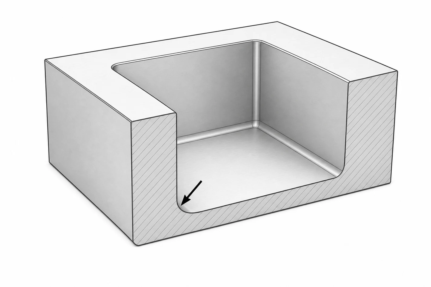
The corner at the bottom of the pocket is different. It is the transition from a vertical wall into the horizontal floor. A square end mill can leave this wall-to-floor intersection nominally sharp.
We’re going to talk about that bottom fillet, added intentionally. The fillet is not an unavoidable artifact of a round cutter. It is a structural feature, and the designer has to decide whether the reduction in stress is worth the extra material and machining.
Why A Floor Fillet Reduces Stress
Imagine the pocket wall as a cantilever growing out of the floor. A force on the wall has to travel through its root and into the surrounding material. At a perfectly sharp corner, the geometry asks that load path to change direction over zero distance. The load crowds into the corner.
A fillet spreads that turn over a finite distance. The peak stress falls and the corner becomes less attractive as a place for a fatigue crack to start. This is the same reason shoulder fillets appear on shafts, ribs blend into skins, and brackets rarely meet their bases with a sharp corner.
The part thickness is the material left between the pocket and the outside face beside it. This matters because it determines the rest of the area that the load flows through.
These two dimensions meet at the fillet. Either may be the thinner load-carrying member, and changing either one changes the local stiffness and the way load reaches the corner.
Moving from effectively sharp to a small radius produces a large reduction in peak stress. Increasing the radius further keeps helping, but each increment eventually buys less than the one before it.
Size The Radius With The Manufactured Geometry
Do not run FEA with a perfectly sharp bottom corner and treat its reported maximum stress as a physical answer. A zero-radius reentrant corner creates a singularity in a linear-elastic model. Refining the mesh makes the reported peak continue upward instead of converging.
COMSOL’s documentation and SOLIDWORKS Simulation guidance both identify that mesh-dependent rise as the characteristic signature of a sharp-corner stress singularity.1,2
The solver is not broken. The geometry is asking a continuum model to turn a load through a point. Model the radius that will be manufactured. If the value is not known yet, parameterize it and solve several candidates. Hold the wall thickness, floor thickness, loads, constraints, material, and tangent locations constant so the radius is the variable being tested rather than one of several simultaneous geometry changes.
For each candidate radius:
- Refine the mesh locally along the complete fillet
- Confirm that the stress at the physical fillet converges as the mesh is refined
- For a ductile material, consider equivalent (von Mises) stress when yielding is the concern
- Compare stress range, surface condition, and fatigue margin for cyclic loading
How A Ball End Mill Changes The Pocket
The ordinary pocket operation is simple: a flat end mill removes material, finishes the floor, and finishes the walls. Adding a floor fillet usually means leaving stock at the root and returning with a ball end mill or bull-nose tool to blend the floor into the wall.
A ball end mill has a hemispherical end. If its radius matches the floor fillet, the shop can place the center of that sphere at the fillet’s center of curvature and drive the tool along the root of the wall. One contour pass sweeps the required quarter-round instead of approximating it with many adjacent passes.
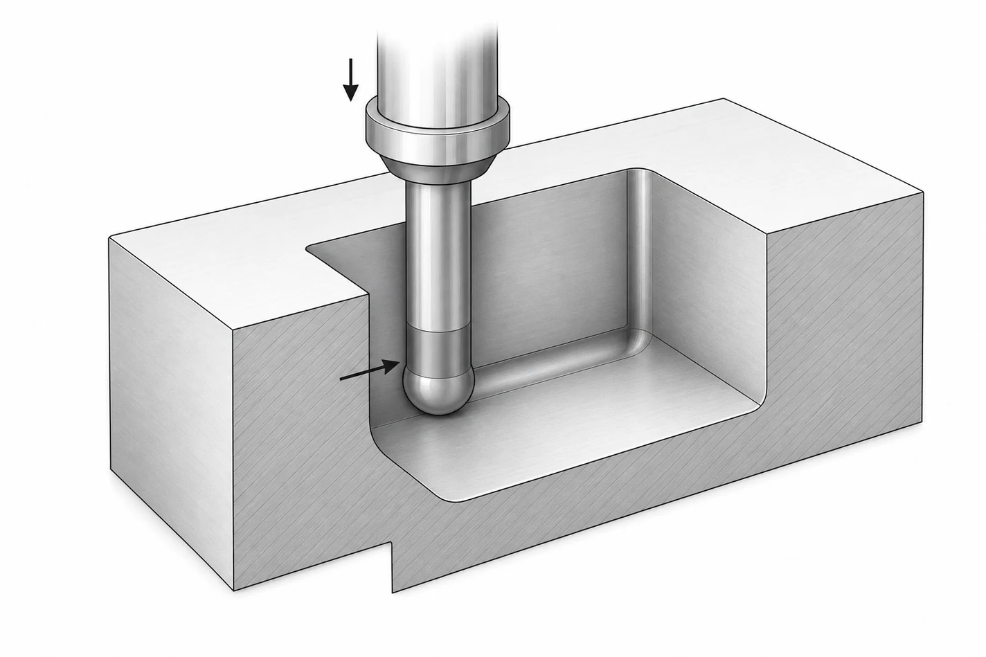
A bull-nose or corner-radius end mill is a different tool: it has a mostly flat bottom joined to its cylindrical side by a smaller corner radius. When that tool radius matches the part, it may finish the flat floor and the root fillet in the same operation.
A ball end mill is usually the more flexible choice for a large floor fillet; a bull-nose tool is useful when the design needs a smaller root radius and a broad flat floor.
An arbitrary radius is still machinable. The shop can use a smaller ball end mill and generate the surface with multiple passes, but the cost moves into cycle time, step-over, blending, and inspection. More passes also create more opportunities for scallops or a small witness line near the tangent between the floor, fillet, and wall.
Larger is therefore not automatically more expensive. A larger standard ball radius may allow a larger, stiffer tool and a cleaner finish. The real cost drivers are whether the radius matches available tooling, whether the tool can reach it, and whether the fillet can be finished without an awkward three-dimensional toolpath.
Surface Finish Is Part Of The Fillet
The highest tensile stress often sits on or near the fillet surface, so the surface left by machining matters when fatigue controls.
Surface valleys behave like small notches. Work on 6061-T6 aluminum simplifies measured surface topography into a field of elliptic micro-notches, derives a stress concentration factor from it, and predicts fatigue life to within about sixteen percent of test results.3 Bending-fatigue testing on high-strength steel reaches the same conclusion from the other direction: rougher machined surfaces shorten life.4
Surface roughness is not the only machining variable that can affect fatigue. Machining also changes near-surface residual stress and material condition; a U.S. Army study of net-shape machining identifies roughness, surface-layer material properties, and residual stress as fatigue-design considerations.5
For a static, ductile part with ample margin, the normal machined finish may be adequate. For a fatigue-critical corner, inspect the actual tool marks, cusps, gouges, and witness lines at the fillet, especially if the fillet is cut by a smaller ball end mill using interpolation passes.
A matching ball or corner-radius tool can create the surface with a continuous contour pass. A smaller ball end mill can generate a larger or compound fillet, but its step-over leaves scallops that should be included in the finish requirement and fatigue assessment.
Do not apply a tight radius tolerance by reflex. If strength only establishes a minimum and packaging establishes a maximum, communicate those functional limits. Giving the shop a usable range can let it select a standard ball end mill without changing the structural intent.
If tangent continuity or surface finish controls fatigue life, specify those requirements explicitly instead of hiding them inside an arbitrary three-decimal radius. Repeated floor fillets should use the same radius when the load and packaging permit. One tool, one finishing strategy, fewer opportunities for the machinist to learn new profanity.
The Practical Rule
For a CNC pocket floor fillet:
- Identify the wall-to-floor corner carrying the load
- Normalize candidate radii against the local load-carrying portions of the part
- Sweep several radii in FEA or use a stress-concentration chart that matches the geometry and loading
- Find the inflection where more radius produces little additional reduction in the governing stress or fatigue metric
- Round upward to a standard ball-end-mill radius when clearance and mass permit
- Analyze the minimum manufactured radius and include the real surface condition when fatigue matters
As always, speak to your machinists. They’ll save you time in picking the right radius available with tooling standard to their shop.
References
- COMSOL AB. COMSOL Multiphysics Reference Manual, geometry reference. doc.comsol.com
- Dassault Systèmes. “Assessing Stress Hot Spots,” SOLIDWORKS Simulation Help, 2023. help.solidworks.com
- Yang, Y., Chen, H., Feng, W., Xu, S., Li, Y., and Zhang, R. “Fatigue life analysis for 6061-T6 aluminum alloy based on surface roughness.” PLOS ONE, Vol. 16, No. 6, 2021, e0252772. doi:10.1371/journal.pone.0252772
- Cheng, Z., Zhu, X., Dong, Z., and Zhang, Y. “Fatigue Life Prediction of Machined Specimens with the Consideration of Surface Roughness.” Materials, Vol. 14, No. 18, 2021, Art. 5420. doi:10.3390/ma14185420
- U.S. Army Research Laboratory. “The Effects of Net-Shape Machining on the Performance of Al…” DTIC accession ADA528052. govinfo.gov